Overall Purpose:
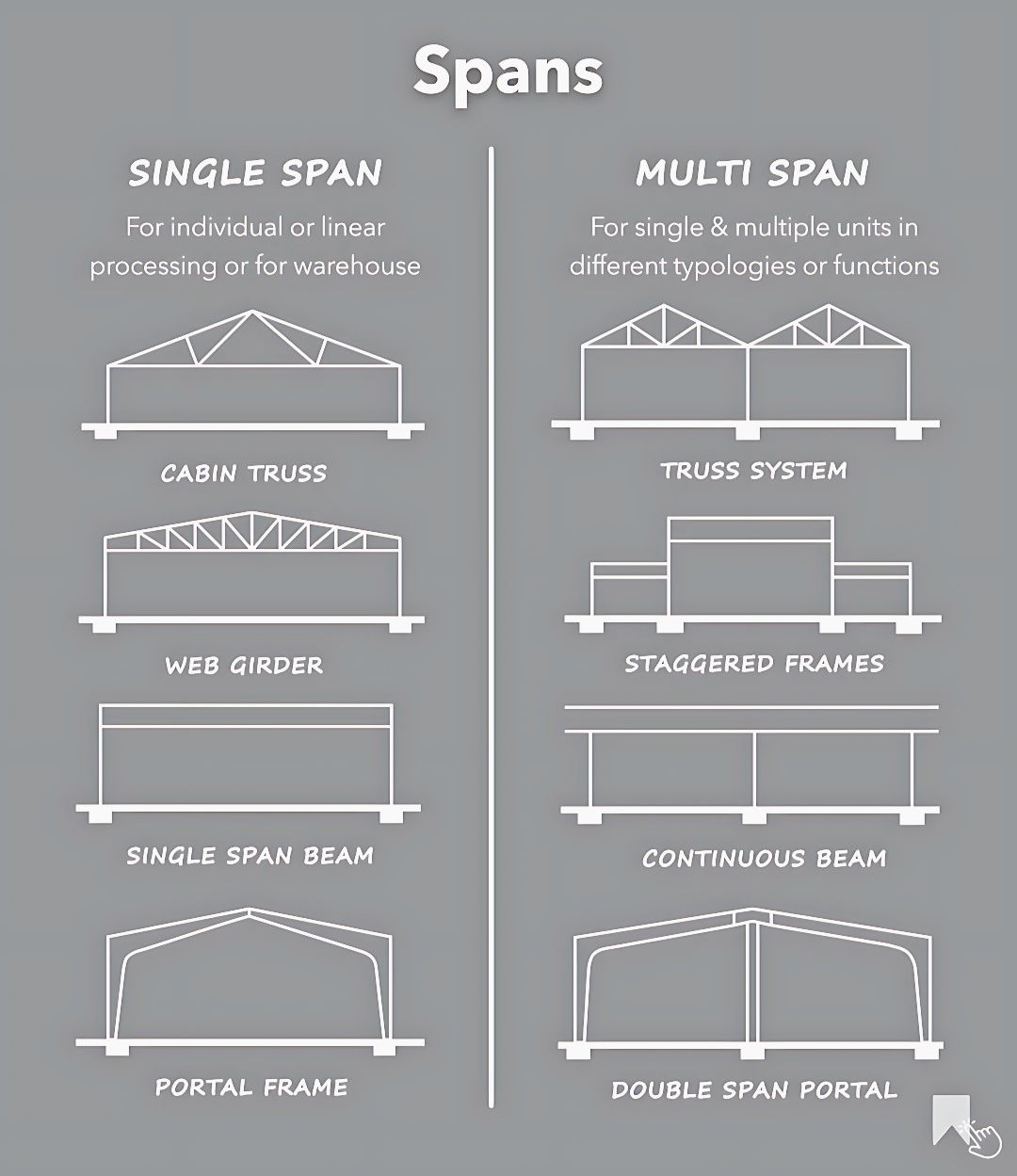
This graphic serves as a concise visual primer on fundamental structural spanning concepts in building design. It quickly differentiates between structures designed for a single open bay and those engineered to efficiently cover multiple connected bays, showcasing various common structural forms within each category. This information is foundational for understanding how buildings are designed to support loads and enclose space.
I. SINGLE SPAN:
* Definition: “For individual or linear processing or for warehouse.” This implies structural systems designed to cover a single, continuous open space, typically without intermediate supports. They are common for straightforward buildings, production lines, or storage facilities.
* CABIN TRUSS:
* Diagram: A triangular truss structure forming a pitched roof. It consists of multiple interconnected members (often steel or wood) arranged in a series of triangles.
* Function: Efficiently spans large distances by distributing loads through tension and compression in its members. “Cabin truss” might refer to a specific type or a simple gable truss.
* WEB GIRDER:
* Diagram: A deep, typically rectangular beam with an open web pattern (like a series of triangles or rectangles) between its top and bottom chords. This is essentially a type of open-web joist or trussed beam.
* Function: Offers high strength-to-weight ratio, allowing for long spans without excessive depth. The open web allows for routing of mechanical systems (ducts, pipes) through the girder.
* SINGLE SPAN BEAM:
* Diagram: A simple, solid rectangular beam supported at two ends.
* Function: The most fundamental spanning element. It carries loads by bending. While conceptually simple, its practical span is limited by its material and depth compared to trusses or girders.
* PORTAL FRAME:
* Diagram: A rigid frame consisting of two vertical columns rigidly connected to a horizontal beam or rafter at the top, forming an “arch” or “goalpost” shape.
* Function: Designed to resist both vertical and lateral (sideways) loads through its rigid connections, often used in industrial buildings, barns, or spaces requiring large clear spans without internal bracing.
II. MULTI SPAN:
* Definition: “For single & multiple units in different typologies or functions.” This describes structural systems that extend over multiple continuous spans, often with intermediate supports. They are used for larger buildings, complexes with varied functions, or when economy of materials is achieved through continuity.
* TRUSS SYSTEM:
* Diagram: Shows multiple connected triangular trusses, often with shared intermediate columns.
* Function: Similar to a cabin truss, but extended over multiple bays. Sharing supports can be more economical for very large structures, providing continuous roof support.
* STAGGERED FRAMES:
* Diagram: Appears to show multiple building sections or frames that are offset or stepped vertically, creating different floor or roof levels.
* Function: This approach can be used to accommodate varying functional requirements, create architectural interest, or optimize for site topography. Each “staggered” section could be a single or multi-span system in itself.
* CONTINUOUS BEAM:
* Diagram: A long, solid beam that extends over three or more supports (not just two).
* Function: By connecting over multiple supports, a continuous beam can achieve greater spans or carry heavier loads with the same beam depth compared to multiple single-span beams. This is because it distributes bending moments more efficiently.
* DOUBLE SPAN PORTAL:
* Diagram: Two interconnected portal frames, sharing a central column.
* Function: Extends the concept of a single portal frame to cover wider areas, maintaining clear spans within each bay while efficiently transferring loads to the ground through shared supports.